← All projects

Case №07 · System development

Vacuum furnace: from separate components to a Siemens system

A development plant with some of the mechanics and control cabinets in place, but no finished electrical design or control software. Step by step it gained electrical documentation, a Siemens ET 200SP, an automatic sequence with vacuum, argon and controlled heating, a three-level alarm concept and a custom WinCC Unified SCADA.

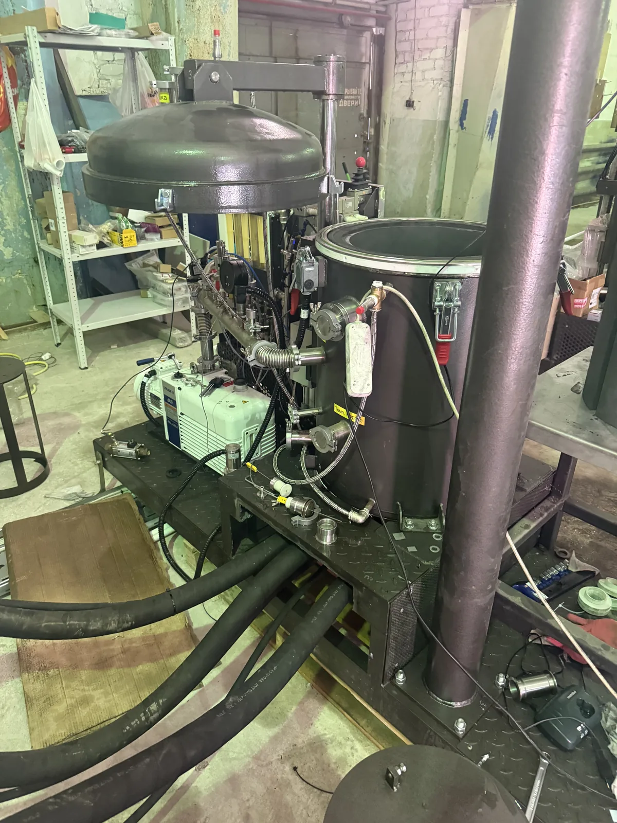
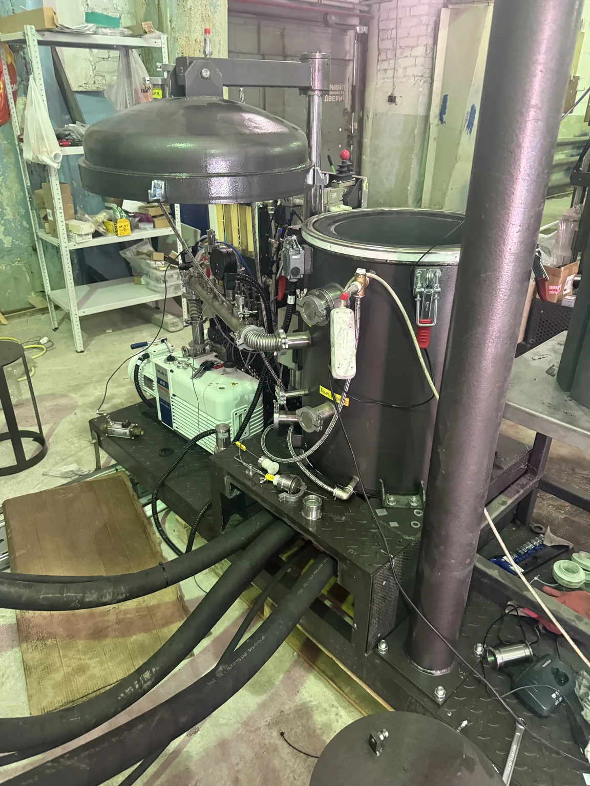
Vacuum furnace: chamber with raised lid, vacuum pump and power cables
Power section180 kVA

furnace transformer · up to approx. 4720 A secondary

Location / working method
Volgograd, Russia · on site
Year
2026
Focus
System development · Siemens + WinCC Unified

01 / Starting point

Not a series machine, but a plant still in development.

The customer was looking for a Siemens programmer for a new and technically unusual vacuum furnace. When I started, much of the mechanics was in place, the control cabinets were standing, part of the electrical equipment had been purchased and some power and process components were installed. But the plant had never run as a complete automated machine – a full regular process had not yet taken place.

The original plant designer was no longer available. So the first job was to work out what existed, what could be reused, what was missing, where wiring had to change, which sensors and actuators were needed, how the process should work and which safety and process conditions had to be considered.

The first step was an on-site survey: inspecting the plant, recording the existing components and cabinet condition, checking mechanical and electrical interfaces, sensors and actuators, reviewing the available documents – and deciding what to keep and what to change.

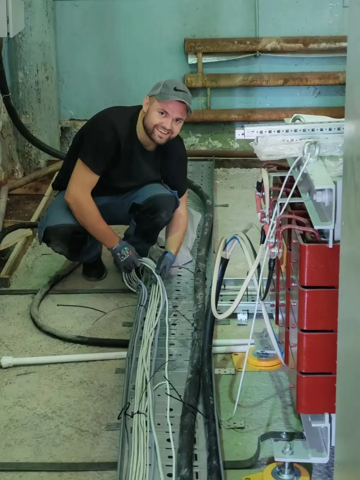
My usual focus is design, PLC/HMI programming, diagnostics and commissioning. In this project I also helped with parts of the installation and wiring, because the plant was already partly assembled and many changes had to be made directly on the real build.
02 / My scope of work

The whole technical chain – not just a program.

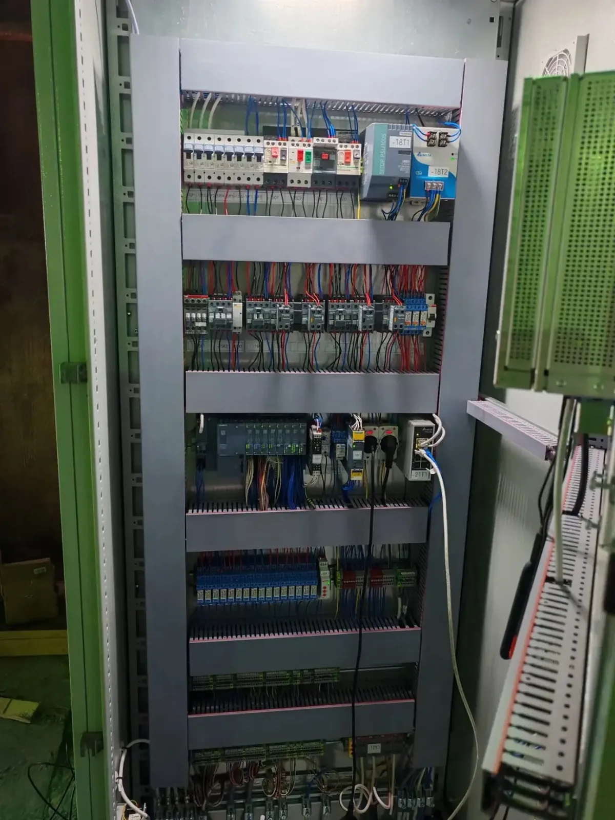
Control cabinet with ET 200SP station, relays and terminals
  1. 01

    Technical survey of the existing plant

  2. 02

    Functional sequence: process steps and transition conditions

  3. 03

    I/O structure, selection and review of sensors and modules

  4. 04

    Electrical design, creating and revising the circuit diagrams

  5. 05

    Adapting the cabinets, partly helping with installation and wiring

  6. 06

    Siemens PLC software: operating modes and the automatic furnace process

  7. 07

    Heating control and temperature control

  8. 08

    Vacuum and argon logic, cooling system control

  9. 09

    Alarm, warning and interlock logic

  10. 10

    Custom SCADA in WinCC Unified, HMI/PLC communication

  11. 11

    Commissioning the Siemens IPC: runtime, users, autostart, kiosk

  12. 12

    Real function and heating tests, analysis of plant behaviour

Electrical design

The diagram has to match the real plant.

The existing build had to be traced on the real plant and documented in a structured way. The documentation mattered not only for the build: it was the basis for PLC programming, I/O testing, troubleshooting, commissioning and later maintenance and extension.

The cabinets were adapted to the real configuration. Existing components were reused where sensible; missing or unsuitable ones were added or earmarked for addition.

Documented, among others

  • infeed, main switch, heating transformer
  • thyristor power controller, power distribution, 24 V supply
  • PLC hardware: DI, DO, AI, AO, RTD/thermocouples
  • vacuum and pressure sensors, flow and level monitoring
  • pumps, fans, argon valves
  • lid switches, emergency stop circuit, safety relay
  • indicator lights, network, industrial PC
  • terminals, cables and equipment identification
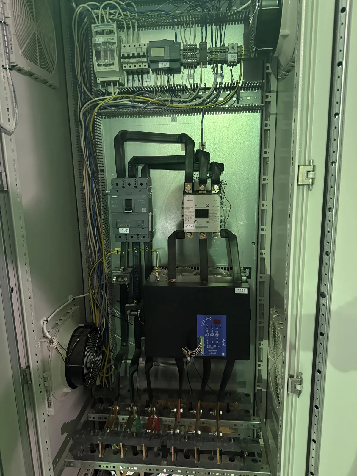
Power cabinet: circuit breaker, heating contactor and thyristor power controller

03 / Automatic process

Fifteen steps from start check to opening release.

Automatic mode runs the furnace process step by step. In addition there is a basic/initialisation state, a manual/service mode for testing individual units (basic interlocks and protective functions remain active), fault states and defined start and restart conditions.

  1. Check start conditions
  2. Lid closed and locked
  3. Evacuate the chamber
  4. Reach the required vacuum
  5. Hold vacuum / leak check
  6. Argon filling
  7. Check argon pressure
  8. Heating release
  9. Controlled heating
  10. Reach target temperature
  11. Holding phase
  12. Controlled cooling
  13. Cool to safe opening temperature
  14. Pressure equalisation / venting
  15. Process end and opening release

Vacuum

The vacuum pump evacuates the chamber and pressure is monitored continuously. The process reacts to insufficient vacuum, timeout, implausible readings, pump fault, missing feedback and unexpected pressure rise. A hold test assesses whether the vacuum stays stable.

Argon

After the vacuum phase, argon is admitted. Argon pressure, hysteresis, valve feedback and settling times are considered. The number of filling attempts before heating is limited by a parameter – if the required state is not reached, the plant does not keep trying indefinitely.

Heating release

Heating is only released when the conditions are met: no emergency stop, safety circuit OK, correct lid state, vacuum phase completed, argon pressure in range, plausible temperature signals, cooling ready, power section ready and no critical fault.

Heating and holding

The temperature is not driven with static full power but guided: target temperature, heating rate, running setpoint, controller, power limit and setpoint/actual deviation monitoring. Holding time only runs while the actual temperature is really within tolerance – merely reaching the setpoint curve is not enough.

Cooling and opening

After holding, the setpoint is lowered in a controlled way. Heating can slow down cooling that is too fast, but cannot speed up cooling that is too slow without active cooling – this is taken into account. Opening is released only at a safe temperature and pressure; the safe opening temperature is adjustable.

Resume

After an interruption the process does not blindly continue anywhere. Depending on the step, the length of the interruption and the temperature deviation, restart conditions are evaluated.

04 / Power section and heating

Very low voltage, extremely high current.

180 kVAfurnace transformer
380 V / approx. 274 Aprimary side
22 V / up to approx. 4720 Asecondary side
approx. 300 Athree-phase thyristor controller

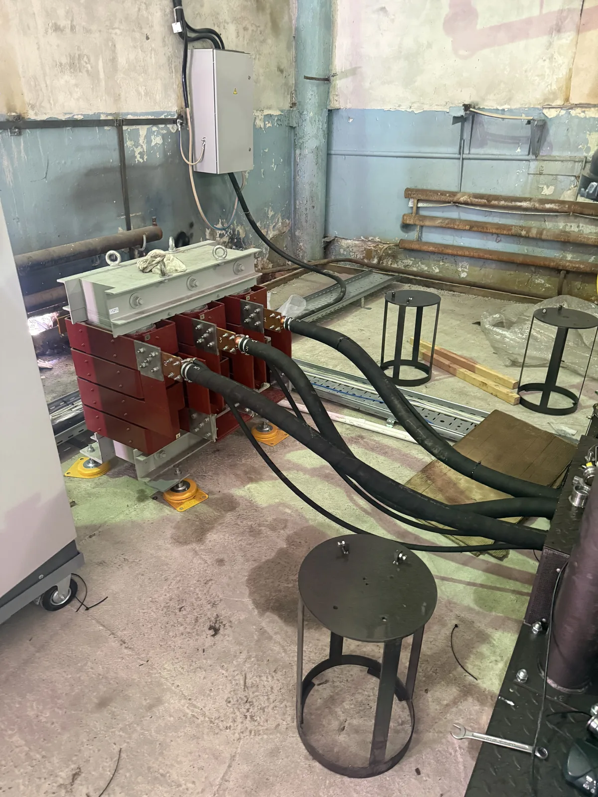
The load is a graphite heater. A three-phase thyristor power controller sits upstream of the transformer; the PLC sends the heating power setpoint via an analogue output. The transformer has its own power path with main switch and heating contactor. So this is not only about small control signals but a real high-current heating circuit with several thousand amperes on the secondary side.

First heating tests

The first heating test was deliberately not yet run as a complete automatic process. The aim was to check the power section, activate the graphite heater, assess the current path and observe the thermal behaviour.

It revealed a design weak point: the transition between the current feed point / power cable and the graphite heater was not yet optimal mechanically and electrically. At several thousand amperes, poor contact resistance is especially critical. The plant basically worked and the heater got warm – but the contact point needed rework.

Commissioning was deliberately paused at this point so the customer could improve the mechanical contact block. After the rework, the heating tests continued.

In the documented test the furnace heated from about 10 °C to about 500 °C at a constant heating power of around 30 %, with a nearly linear temperature rise. This gave the first real data on the plant’s thermal behaviour – the basis for controller tuning and further process optimisation.

Furnace transformer and power cables to the heater

Cooling and sensors

Six cooling circuits in the heating release.

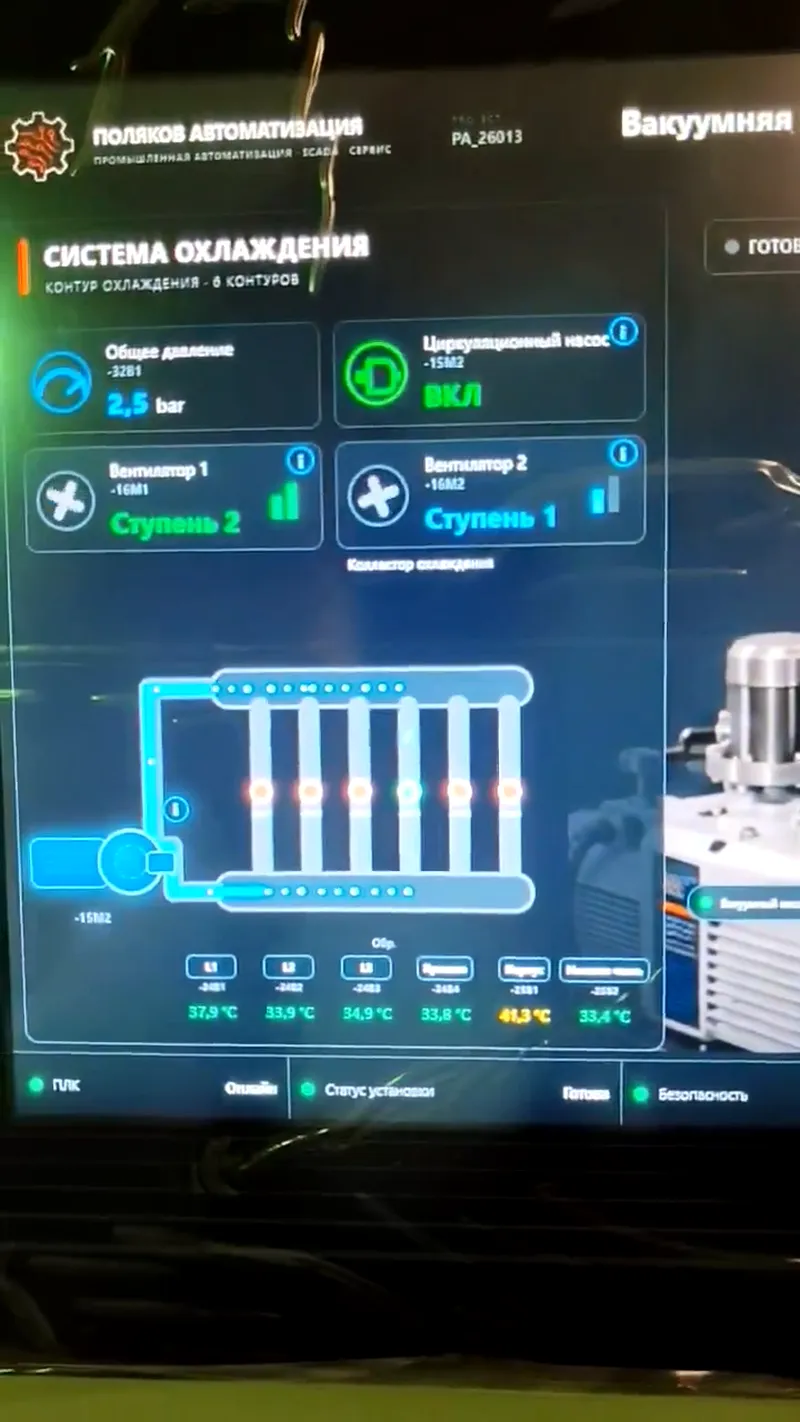
Cooling is a key area in its own right. The visualisation shows six circuits, including L1, L2, L3, lid and housing areas. A mechanical flow switch gives each circuit a digital flow-OK signal; coolant temperatures are measured with PT100 sensors. Cooling is tied directly into heating release and alarm reaction: a critical cooling failure during heating can shut the heating off immediately.

Measuring points

  • workpiece temperature: Optris pyrometer, non-contact, analogue + fault signal
  • vacuum: Edwards APG100 (active Pirani gauge), Seneca signal converter, additional threshold signal
  • argon/chamber pressure: WIKA S-20, 4–20 mA
  • coolant pressure: 0…10 bar, analogue
  • type K thermocouples between insulation and housing/lid
  • limit switches for lid state

Monitored

  • coolant pump and coolant pressure
  • flow per circuit
  • supply and return temperatures
  • lid, housing and transformer temperatures
  • level in the coolant tank

The PLC evaluates not only commands but also motor protection, contactor feedback, thermal contacts and valve feedback, so faults like "command present, feedback missing" are detected specifically. The electrical values of the three phases – currents, voltages, power, cos φ, frequency, energy, unbalance – come from a Siemens SENTRON PAC2200 via Modbus TCP; selected values are shown in the SCADA.

Alarms and interlocks

Three reaction levels instead of one "fault".

The plant got a message matrix with about 178 conditions covering cooling, heating, general monitoring, sensors, feedback, process conditions and communication/system states. More important than the number is the principle of a graded reaction.

Level 1

Immediate shutdown

  • heating setpoint 0 % immediately
  • block thyristor, heating contactor off
  • interrupt process, lock restart
  • keep post-cooling running while safely possible
Level 2

Power limitation

  • limit heating power to a configurable maximum
  • no new process start
  • continue the running process in a controlled way if safe
  • escalate to level 1 if it gets worse
Level 3

Warning

  • show a warning
  • process may continue under safe conditions
  • watch state and trend
  • escalate depending on duration or count

Besides the PLC logic, the plant has hardware safety components: emergency stop, a Siemens safety relay with feedback, lid contact and monitoring of the heating contactor and main switch. An emergency stop must not be delayed by a slow sequence: the PLC evaluates the states, while the actual shutdown is handled by the intended safety/hardware structure.

Implemented or provided interlocks include: no heating start without release, with a critical cooling fault or implausible process conditions; no uncontrolled simultaneous valve operation; restart lock after critical faults; opening release only at safe temperature and pressure. The message matrix is an engineering basis and does not replace a formal risk assessment of the complete machine.

Software architecture

Modular software with clear responsibilities.

  • clear separation of inputs, process logic, operating modes, alarms and outputs
  • modular function blocks with defined responsibilities
  • requests processed separately from final device commands
  • centralised alarm and safety structures
  • unambiguous HMI → PLC and PLC → HMI interfaces
  • as few unstructured cross-links as possible – easy to maintain and extend

Path of an operator command

  1. HMI command
  2. PLC interface
  3. Mode & process logic
  4. Interlocks
  5. Final output

An operator command never writes unchecked to a hardware output. In the other direction, the PLC prepares states and measurements and provides defined data to the SCADA. This improves safety, diagnostics, traceability and maintainability.

Process and customer parameters survive a power cycle – for example a changed vacuum setpoint. Buttons and commands such as Start, Stop or Reset are deliberately not retentive: after a restart, neither a start command nor a manually opened valve becomes active again from an old state.

05 / SCADA

A custom visualisation on the real IPC.

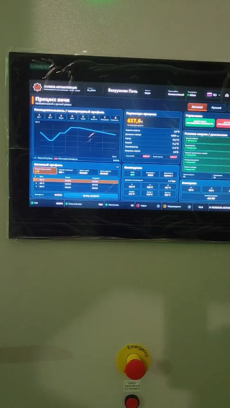
The visualisation was built specifically for this plant with TIA Portal V20 and WinCC Unified V20 PC Runtime on a Siemens SIMATIC IPC477D. The goal was not a standard HMI of grey rectangles but a modern, technically clear plant view – designed for the real IPC resolution of about 1366 × 768 rather than only a full-HD engineering monitor.

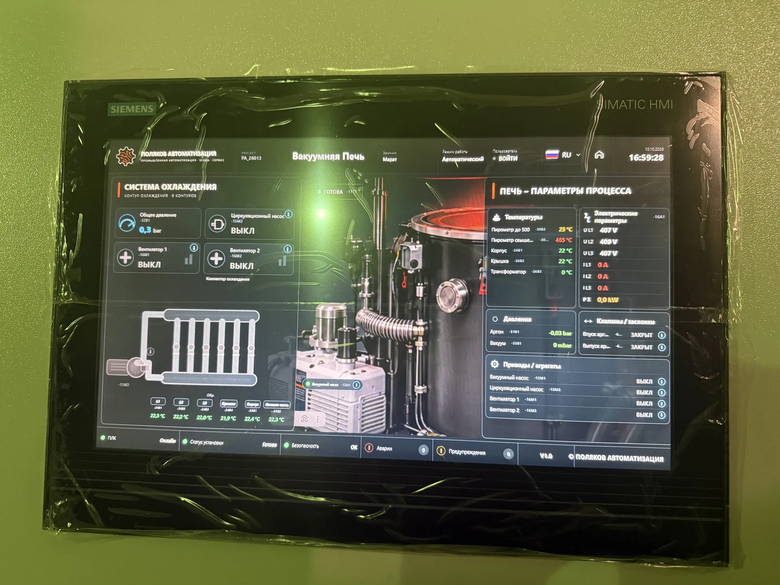
The main overview shows cooling on the left, the furnace in the centre and process data on the right: heating status, pyrometer temperature, housing, lid and transformer temperatures, vacuum, argon pressure, valves, pumps, fans, cooling circuits and the PAC values L1/L2/L3. When heating is active, the furnace is shown as active.

Coolant flow is animated with particles moving along the pipes – a pure CSS/SVG stroke animation was not reliably visible on the real Unified Runtime. The animation follows the real state: supply only with the pump running and flow present, each circuit according to its own flow-OK.

SCADA main overview on the IPC: cooling, furnace and process parameters

SCADA functions

  • device pop-ups for pump/motor, two-stage fan and valve: status, stage, feedback, diagnostics, operating hours, start counter
  • temperature and process profiles: targets, ramps, holding times, pressures, hystereses
  • alarms with area, equipment, condition, reaction level and cause hint
  • trends for heating, cooling, pressure and vacuum – for troubleshooting and optimisation
  • customer and service parameters with access rights
  • Russian, German and English – native WinCC texts and custom web controls switch together
  • roles: service/administrator, customer admin, operator

Not just a Windows PC

The IPC should behave like part of the plant: switch on → Windows and Siemens services start → WinCC Unified Runtime starts automatically → the kiosk client opens the plant interface. Commissioning brought typical PC-runtime issues: local users had to be transferred correctly – retained old user management data caused login problems, which were solved by a correct full download; at boot the kiosk sometimes started before the runtime was ready – a delayed kiosk start made it stable. A PC-based SCADA does not end with drawing screens: runtime, users, network, certificates, services, kiosk and boot behaviour also have to be commissioned.

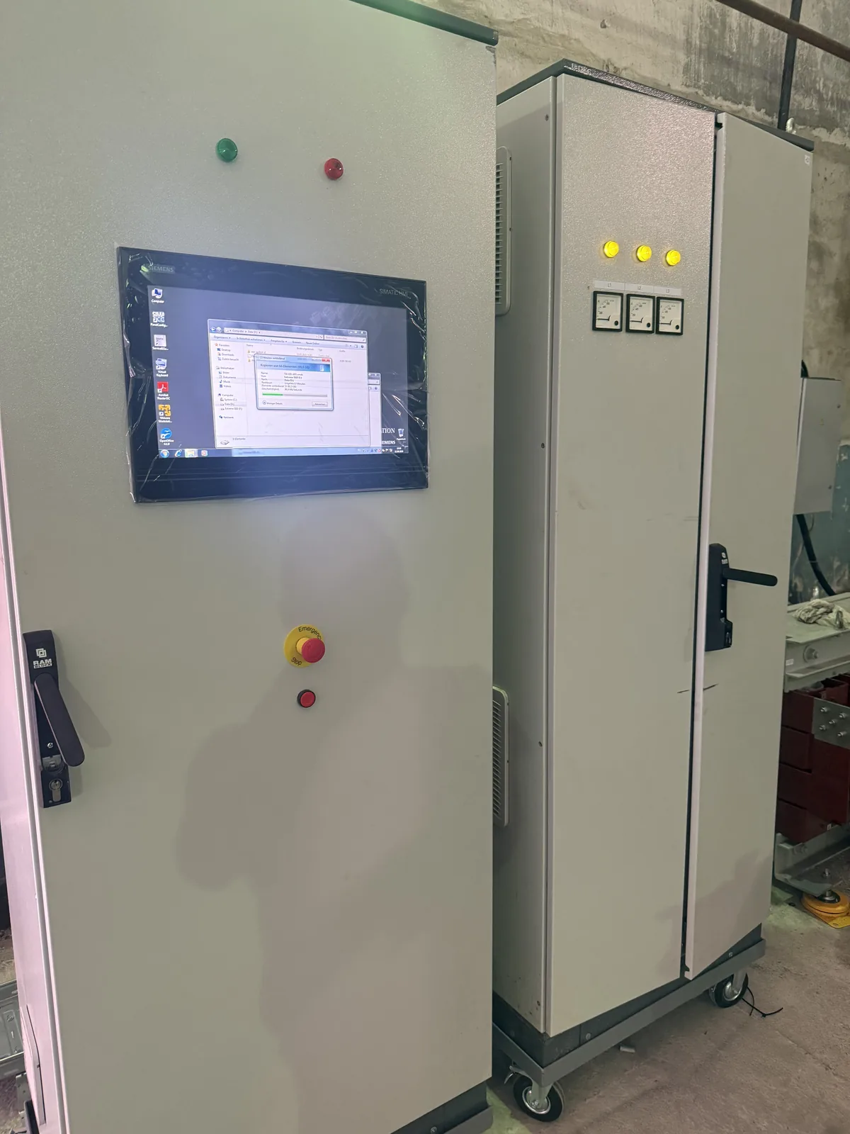
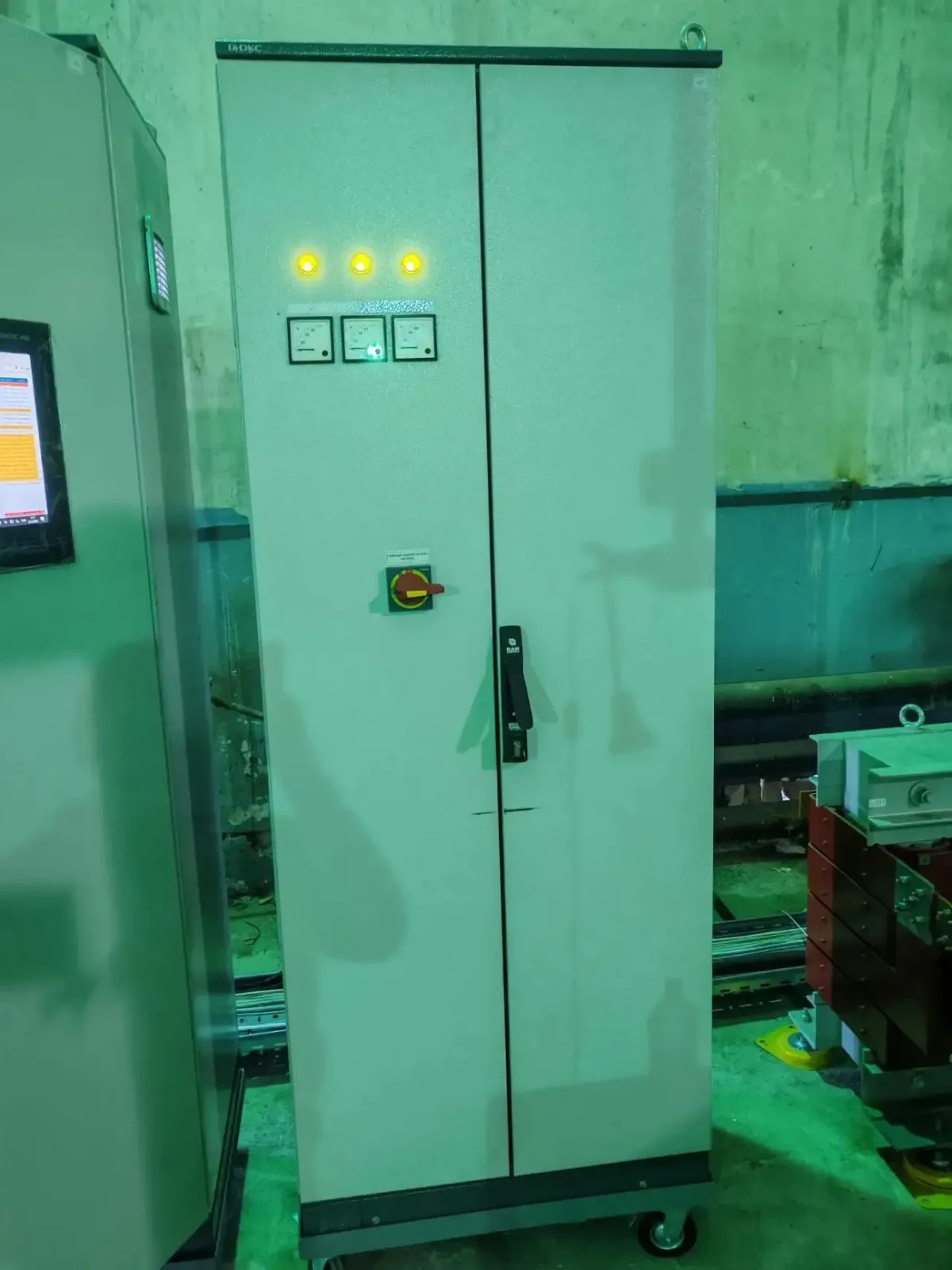
Control cabinet with Siemens IPC next to the power cabinet during setup

What commissioning showed

Much only shows up on the real plant.

Mechanics, power electrics, cabinets, sensors, PLC, control, process, cooling, safety, IPC and SCADA all came together here. A desk test cannot predict everything. Only on site do you see:

  • contact resistance at high-current connections
  • real thermal behaviour and actual heating rate
  • sensor responses and pump and valve feedback
  • mechanical interlocks
  • runtime and IPC behaviour at boot
  • usability on the real touchscreen

06 / Result

An unfinished plant became a structured Siemens automation solution.

The automation was implemented through to real commissioning and heating tests. PLC and SCADA were commissioned on the real plant and the real IPC; the test results are being used to further optimise process and control parameters.

  • Traceable electrical documentation and defined cabinet modifications
  • Siemens ET 200SP / S7-1500 with modular PLC software
  • Automatic sequence with vacuum, argon, temperature guidance and heating power control
  • Cooling monitoring, extensive interlocks and a three-level alarm concept
  • Sensor and actuator diagnostics, electrical energy measurement
  • WinCC Unified SCADA on the IPC477D: three languages, device pop-ups, trends, parameters, user rights, autostart and kiosk
  • Real heating tests with first data on thermal behaviour

Benefits for the customer

  • one central overview of the whole process
  • traceable states and better diagnostics
  • reproducible process parameters
  • clearly defined releases and interlocks
  • maintainable, extendable software
  • temperature, pressure, vacuum, cooling and electrical values in one visualisation

Thank you

Many thanks to the customer for the trust and for this exceptionally interesting project. I enjoyed it a great deal, precisely because electrical engineering, power electronics, process development, Siemens programming, control and SCADA came together so closely here. Projects where a working automation solution emerges step by step from individual components are exactly the kind of work I like most.

— Wladimir Poljakov

POLJAKOV AUTOMATION / NEXT STEP

A similar task at your plant?

Every plant has a different starting point. A short description helps establish the next useful technical step.