Power circuits
Main_Circuit_V1.3.pdfConnections between electrical loads, circuitry and equipment identifiers.
 Wladimir PoljakovIndustrial Automation Specialist
Hardware / Software / Knowledge
The memory
of the machine.
A machine must make sense to more than the person who programmed it.
I create and update electrical drawings, control system descriptions and project records for PLCs, HMI and drives — for operation, diagnostics and future changes.
Technical concept sketch
An illustrative structure, not a real customer document.
Connections. Functions. Versions.
PA—DOC / 01Each part of the machine has a place in the records. Together, these documents connect electrical hardware, software and process function.
The scope and level of detail depend on the task and agreement.
A drawing that no longer matches the machine offers little help. Changed wiring, a replacement component or a software revision should leave a traceable record.
Having a folder is not enough. Its contents must belong to a known machine configuration.
Select a drawing, PLC or HMI revision. The current set is predefined for this example; individual project parts can have different version numbers.
This revision belongs to the current example set. In a real project, its status and correspondence with the machine are verified.
This revision belongs to the current example set. In a real project, its status and correspondence with the machine are verified.
This revision belongs to the current example set. In a real project, its status and correspondence with the machine are verified.
The highest number alone does not prove that a file is current. A defined set, a traceable status and a check against the actual machine are needed.
Open a section and select a file. This is one way to organize a technical handover.
Main_Circuit_V1.3.pdfConnections between electrical loads, circuitry and equipment identifiers.
Control_Circuit_V1.3.pdfControl circuits, terminals and device connections.
IO_List.xlsxSignals, channel assignments and equipment references.
PLC_V2.3.zipSource project, revision and notes on the required engineering environment.
HMI_V1.8.zipVisualization project, tags and operator interface functions.
Drive_Parameters.pdfAgreed settings linked to the particular drive and motor.
Network_Overview.pdfDevices, interfaces and data exchange structure.
Functional_Description.pdfOperating modes, sequences, operational interlocks and function descriptions.
Illustrative preview only. Not a real PDF, backup or downloadable project.
This demonstrates a possible filing structure. There is no portal, file upload or storage of customer data here.
Open a technical sheet. The actual set follows from the available information and the agreed project scope.
Power and control circuits
A traceable software baseline
Operation and visualization
Settings in the context of the machine
Traceable data exchange
What the machine does and why
Not every project includes every item. Scope, formats, source files and handover arrangements are agreed in advance.
From a signal to a real device, and back. Select a route or hover over it.
The drawing associates the PLC command with contactor control and the relevant motor. The power circuit is considered separately.
A channel description connects the sensor, wiring, input and physical meaning of the value in the program.
Device identifiers make the connection between a software command, wiring and actuator traceable.
Simplified functional illustration with fictional identifiers. Not an installation drawing or a description of safety circuits.
After several repairs and modifications, the project may no longer represent reality. Work begins with the available records and the accessible equipment condition.
Reconstruction feasibility and scope are assessed first. Complete recovery of every unknown legacy system cannot be promised.
Years later, it matters not only that a function works, but why. Clear structure preserves knowledge about the machine.
General professional principles only. Internal programming standards and customer source code are not published.
More than a file number: what changed, why it changed and which machine state it belongs to.
Fictional history of a separate example. It does not represent a customer or the version numbers used above.
An up-to-date drawing helps trace where a signal comes from. Without it, connections, wiring and their relationship to the software must be established again.
Documentation can reduce the search effort. No specific time saving is promised.
Migration starts with understanding the existing system. Known I/O, loads, hardware, communication and functions make changes easier to prepare in a controlled way.
Changes made during commissioning need to be captured. Here, as-built means that the records reflect the actual implemented configuration within the agreed scope.
CommissioningAn example review process, not acceptance of a real project. The scope and handover of as-built records depend on the task.
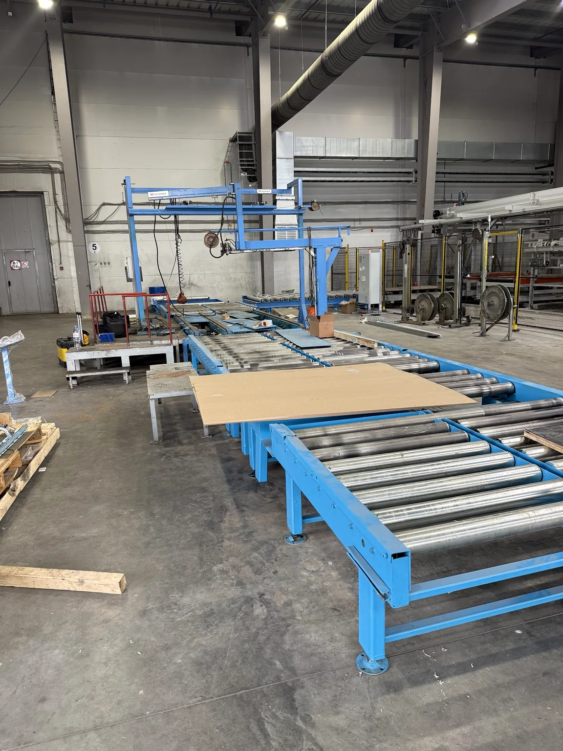
PLC software and HMI were developed for a chipboard transport and packaging line. Documentation and an operating manual were handed over after commissioning.
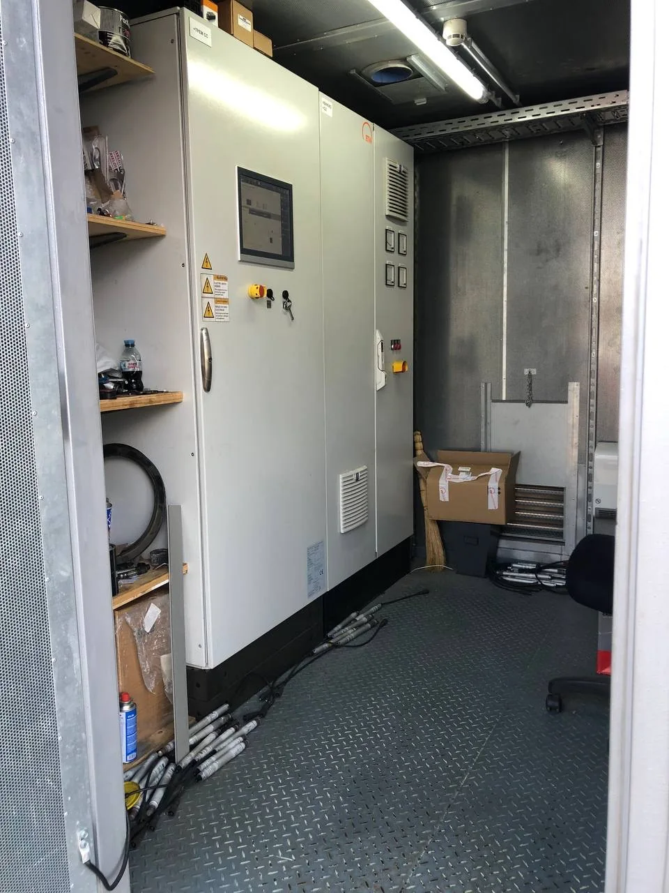
Replacing Weidmüller with ОВЕН ПЛК210 involved electrical drawings, connection diagrams, and dismantling and modification instructions. These supported the customer technicians working under remote guidance.
A small example from a project folder. Choose a filename.
Choose a name to compare.
Even a good name does not prove a file is current. It must match the verified machine state. All filenames shown are fictional.
Yes, the task is assessed after reviewing the original records and equipment condition. Hardware and software access, survey effort and project boundaries determine what can be done.
That cannot be promised in advance. Available drawings, hardware, identifiers, programs and survey access are checked first. The feasible scope follows from that assessment.
No. Drawings, PLC/HMI projects, parameters, I/O lists, descriptions and other records are included within the agreed scope. Formats and source-file handover are discussed separately.
Not necessarily. The current set must be associated with the actual machine and have a traceable status. A number and date help identify a file but do not replace verification.
No. The folders and file previews only demonstrate a possible structure. There is no sign-in, upload, customer file storage or download of real projects.
Send the materials you already have. Reviewing them will help define what documentation needs to be created or updated.
First assess the source information and scope. Then agree the documentation set.