01
A new drive
Selection and technical assessment, configuration preparation and commissioning, taking the motor, control system and installation conditions into account.
Motor → selection → commissioning Wladimir PoljakovIndustrial Automation Specialist
Energy / Control / Motion
From a PLC command to motion in a real machine.
Setup and commissioning of variable frequency drives for industrial equipment. Motor, drive, PLC, communication and mechanics are treated as one system, not as unrelated tasks.
Selection · Setup · Replacement · Integration
One system — a shared result
The PLC determines what the installation should do. Drive setup determines how the motor carries out that command, with appropriate dynamics and an agreed response to changes in load.
More than Start / Stop
Setting up a drive means matching the motor, load and control logic. Starting is only part of the task: acceleration, working speed, braking and responses to deviations matter too.
frequency drive commissionings
Hands-on experience that connects individual parameters to the behaviour of the machine.
Experience across platforms
A key technical focus
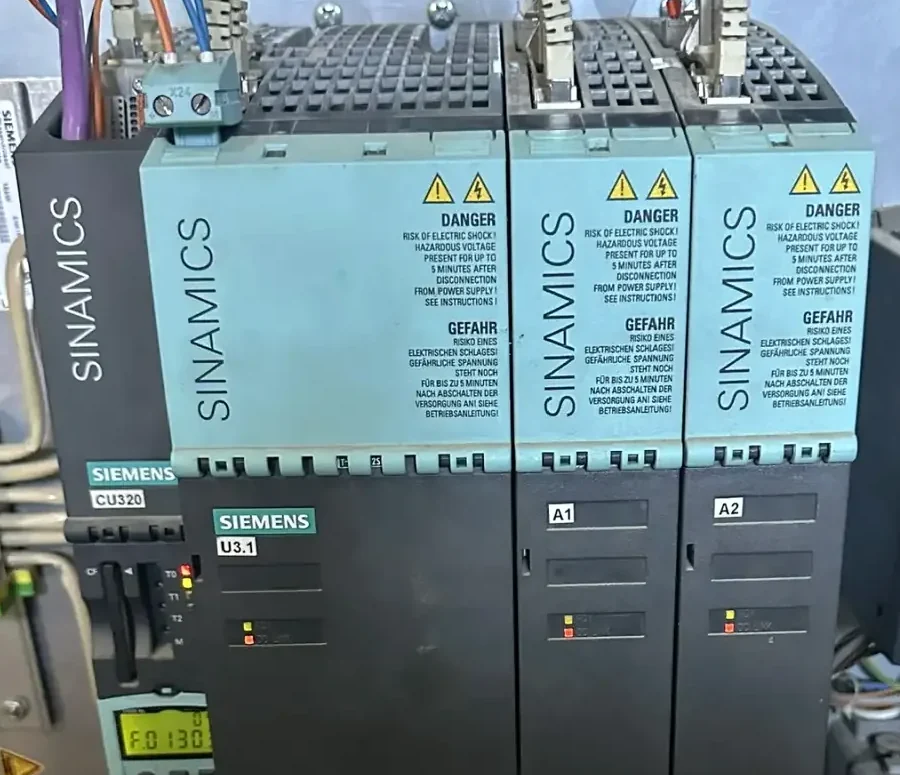
Siemens SINAMICS forms a significant part of my hands-on experience. The appropriate solution is still determined by the task, the motor and the existing control system.
Further hands-on experience
The exact series, functions and integration options are checked against the device documentation. Drives from the same brand do not necessarily have the same capabilities.
From first start to replacement
Selection and technical assessment, configuration preparation and commissioning, taking the motor, control system and installation conditions into account.
Motor → selection → commissioningAnalyse the existing function, identify a suitable replacement and integrate it into the current electrical system and PLC program.
Existing function → new solutionCoordinate setpoints, dynamics and braking with the real load. Behaviour is checked not only unloaded but also in the working process.
Dynamics → load → resultIntegrate control and status words, setpoints, actual values and diagnostic messages into the control system.
Command ↔ stateFind the cause in the interaction of drive, motor, electrical system, PLC and mechanics — rather than repeatedly resetting the same fault.
Cause → solution → verificationKeep the function. Renew the technology.
That does not automatically mean replacing the entire machine. I first examine the motor, electrical system, interfaces and the drive’s role in the process. A technically justified replacement can then be selected.
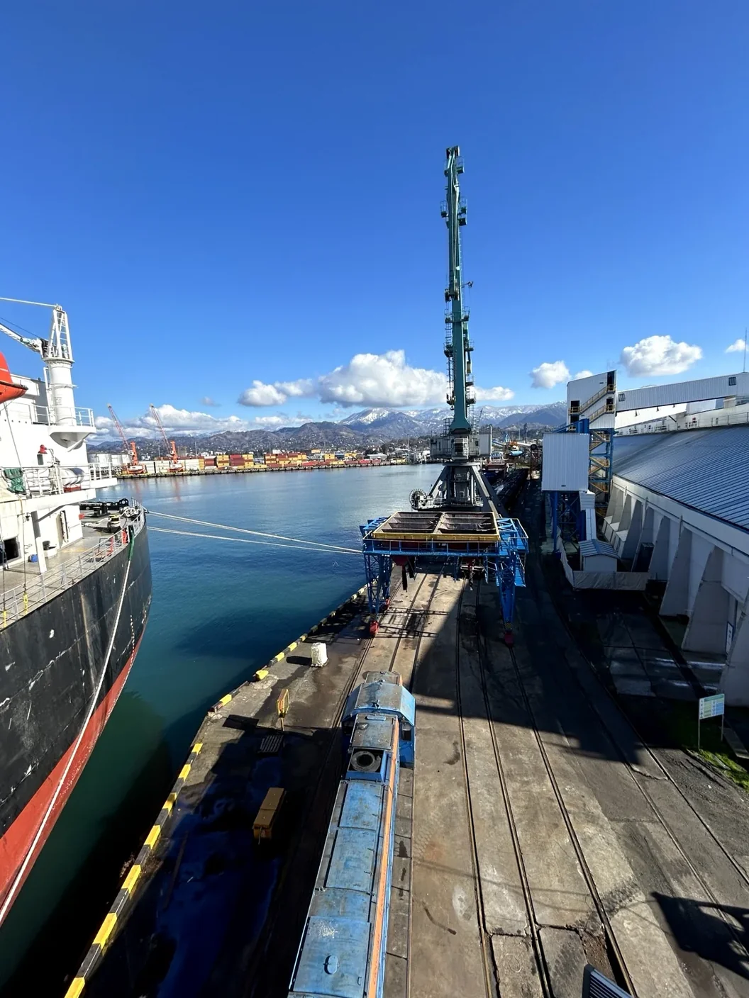
Real project · Case 001
Drive + PLC
In an industrial installation, communication often goes beyond a digital Start/Stop signal. The available interface carries commands, setpoints, states and diagnostic information.
PROFINET, PROFIBUS, Modbus RTU/TCP or CAN — depending on the drive, its options and the controller. Not every device supports every listed protocol.
For the machine — not just the cabinet
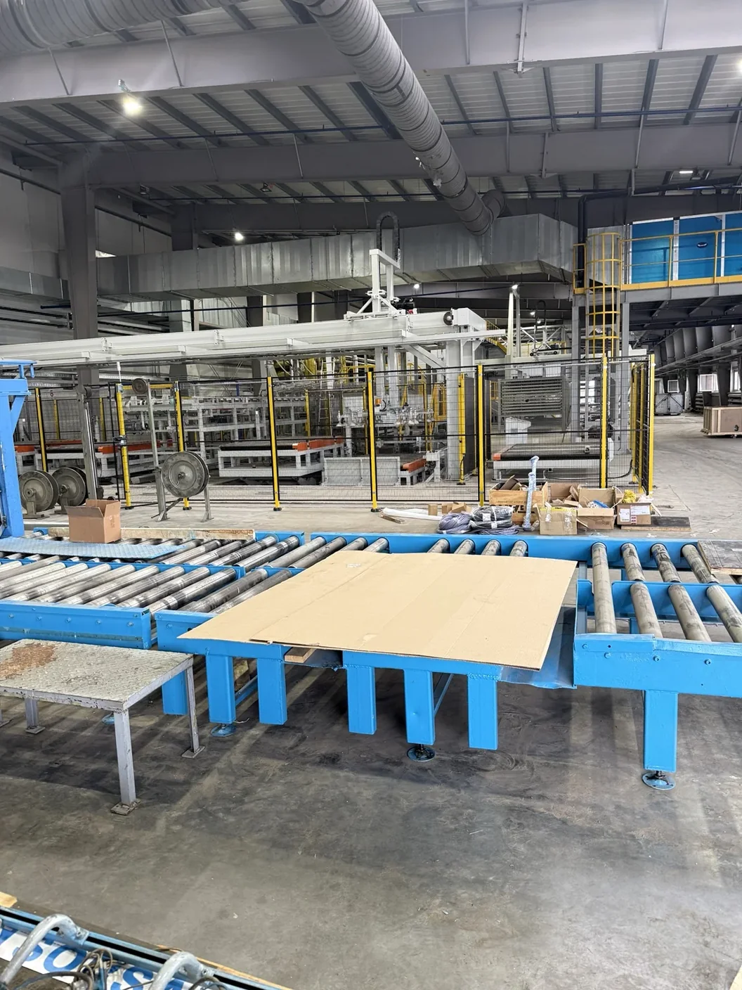
Motor, load, gearing, inertia and the required dynamics jointly determine how the drive should operate. This distinguishes real commissioning from simply entering a few parameters.
Checked in real operation
Commissioning a frequency drive is a closed engineering process: data and commands are checked on the installation, and the results inform further adjustments.
Initial characteristics and the task.
Motor parameters and the selected mode.
Command sources, setpoints and status.
Function checks under agreed conditions.
Mechanism behaviour in the process.
Refine dynamics and reactions.
Check states and the result.
Deviations lead back to the relevant stage. This describes an engineer’s workflow, not instructions for setting up a drive yourself.
Within the agreed scope, I provide parameters and backups, updated drawings, change descriptions and explanations for personnel. The customer should understand the system version they continue to work with.
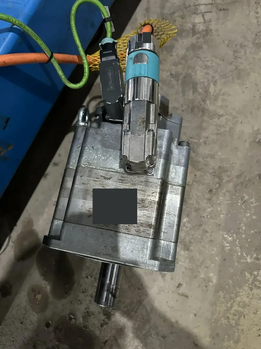
Another example · Case 005
Water ingress into the servo motor had damaged its built-in encoder. Diagnostics confirmed the hardware cause. This case shows why the drive and the motor need to be investigated together.
A servo drive is a distinct drive-system task, not an example of a standard VFD setup.
FAQ
Analysis of the motor and mechanism, operating-mode selection, coordination of setpoints and dynamics, and checks of PLC communication and loaded operation. The exact scope depends on the equipment and the task.
This is assessed after checking electrical data, motor, braking, interfaces and PLC logic. Compatibility and adaptation requirements must be established before replacement.
With suitable access, configuration, communication and diagnostic data can be checked. Measurements, wiring changes and physical checks are performed by qualified personnel on site. Remote-work options are agreed beforehand.
Drive and motor types, a short description of the mechanism and task, existing electrical drawings and control-system details. For faults, saved messages and information about previous work are useful.
A new drive, replacement of an obsolete unit, matching it to the mechanism or PLC integration: send the device type, motor data and a short description. I will review the information and suggest the next technical step.
— Wladimir Poljakov
Call · +7 (928) 455-05-22